Introduction
The ATMEGA 2560 is a 8 bit CPU with 8kByte of SRAM and 256 kByte of Flash. It is capable as an application controller for the iRJ45/SoM module.
ATMEGA 2560 targets are only compatible with uGoal.
Software
Toolchain and flash tool
For compiling the example code, a AVR compiler is required. AVR-GCC can be obtained in several ways. Further information can be found here: http://avr-eclipse.sourceforge.net/wiki/index.php/The_AVR_GCC_Toolchain
For flashing the binary to the board AVRDUDE is required.
# on a MAC
brew tap osx-cross/avr
brew install avr-gcc avrdude

# on Linux
sudo apt-get install gcc-avr binutils-avr gdb-avr avr-libc avrdude

# on Windows using msys2
pacman -S --needed base-devel mingw-w64-x86_64-toolchain
pacman -S mingw-w64-x86_64-avr-gcc
pacman -S mingw-w64-x86_64-avr-libc
pacman -S mingw-w64-x86_64-avrdude
Building
Within a example folder of the software delivery (e.g. projects/ugoal/02_profinet/gcc) build the firmware with following commands:
make PLATFORM=atmega2560 clean all
Flashing
Flashing the firmware is done with the following command. Please use the UART device for your system.
make PLATFORM=atmega2560 UART=/dev/tty.usbmodem141401 flash serial
The Makefile target serial will use minterm.py from the pyserial package. Thus python and pyserial needs to be installed.
Serial Logging
On *nix systems the Makefile target serial can be used to open a serial terminal. This target uses the serial terminal from the pyserial package for python.
On windows systems a dedicated serial terminal should be used for serial logging (e.g. Putty).
Getting Started
Preparations
Hardware Requirements
Make sure following settings are set:
J13 - Connect “iRJ45” with “Sockel”
J8 - Connect “CS_SOURCE” with “PB2”
J7 - Connect “RST_SOURCE” with “PD7”
Set all DIP-Switches to “OFF”
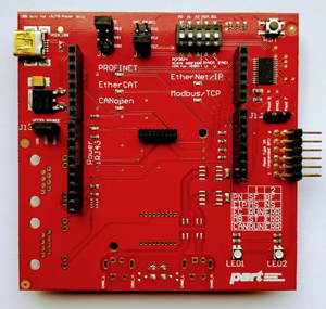
ATMEGA 2560 Board
There is no configuration required.
Target System
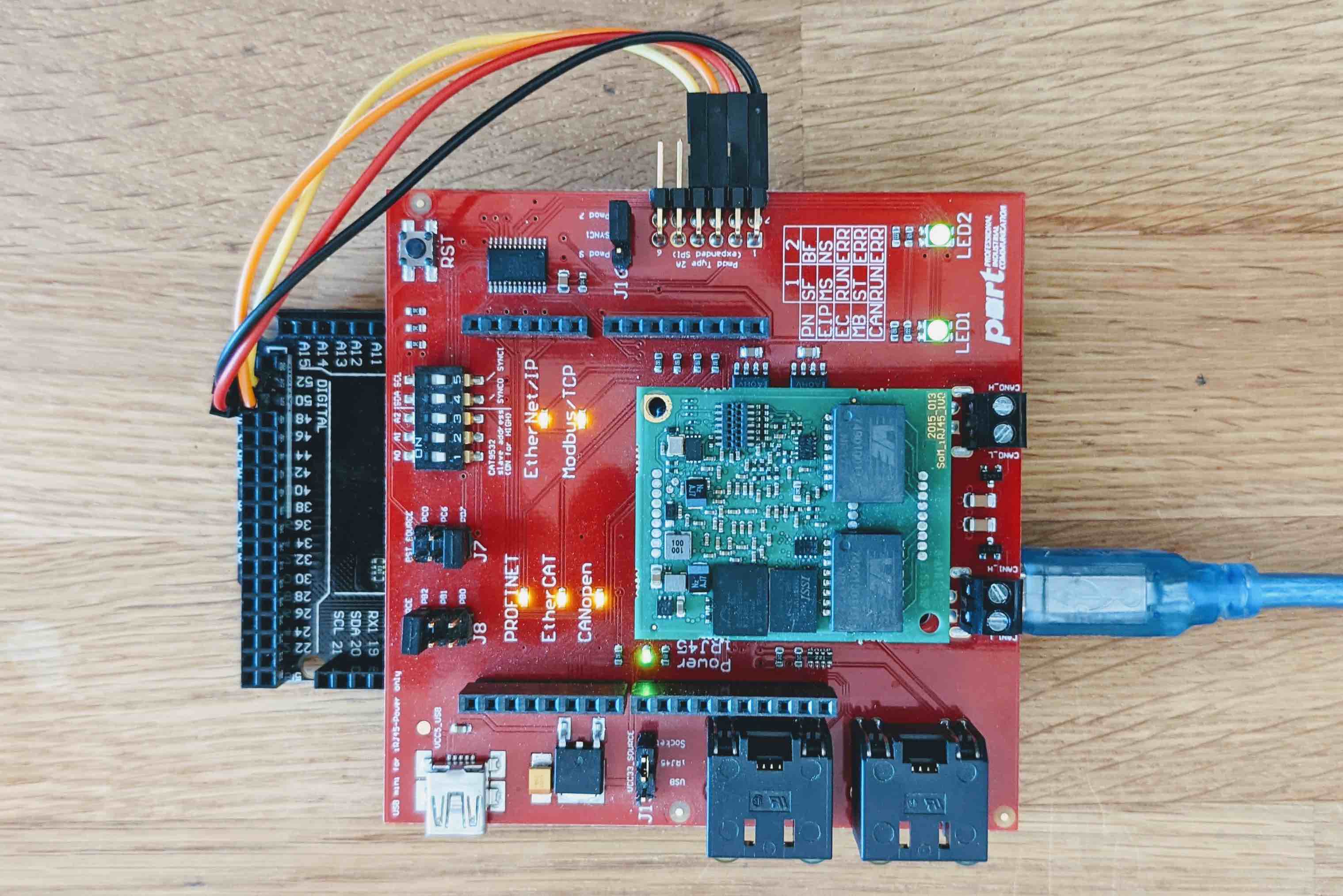
Please connect both boards with each other, before you connect them per USB to your computer.
In order for the SPI connection to work you need to add following wiring:
PMOD connector pin | Arduino pin | Function |
|---|---|---|
1 (CS) | 53 | Chip select |
2 (MOSI) | 51 | MOSI |
3 (MISO) | 50 | MISO |
4 (SCK) | 52 | SCK |
Debugging
UART
The ATMEGA 2560 provides a UART over USB cable. Choose the following settings:
Speed | 28800 |
Data Bits | 8 |
Stop Bits | 1 |
Parity | Odd |
Flow Control | XON/XOFF |
Application 02_profinet
After setting up the serial monitor and starting the debug session, the output should look like this:
[INF] ../rpc/goal_mctc_rb.c:277 creating rpc ring buffer with buffer size 768 and elem size 256
[INF] ../rpc/goal_mctc_rb.c:277 creating rpc ring buffer with buffer size 768 and elem size 256
[INF] ../goal_media/goal_mi_mctc.c:793 rpc transfer size set to 1024
[INF] ../goal_media/goal_mi_mctc.c:723 peer requested Sync Init
[INF] ../goal_media/goal_mi_mctc.c:723 peer requested Sync Init
[INF] ../goal_media/goal_mi_mctc.c:723 peer requested Sync Init
[INF] ../goal_media/goal_mi_mctc.c:723 peer requested Sync Init
[INF] ../goal_media/goal_mi_mctc.c:455 RPC state synchronized, running appl_setup
[INF] ../goal_media/goal_mi_mctc.c:458 configuring timeout values for peer
[INF] ../pnio/goal_pnio_rpc_ac.c:259 PROFINET Application Core successfully started
[INF] ../example/02_profinet/goal_appl.c:188 Initializing device structure
[INF] ../example/02_profinet/goal_appl.c:230 PROFINET ready
[INF] ../goal_media/goal_mi_mctc.c:487 local setup done
[INF] ../ugoal/ugoal.c:212 HEAP utilization: 3400/4096 (83%).
Known Issues
Following you’ll find current limitations regarding the ATMEGA 2560.
Some examples will not work since the platform provides insufficient resources. In general the uGOAL examples will work ( iRJ45 / SoM - uGOAL Examples ). Examples from the 20215013_irj45 folder ( iRJ45 / SoM - GOAL examples ) may need additional resources. This is specially the case when web server and tcp/udp channels are used in addition to a fieldsbus protocol.