Disclaimer
This manual represents the current state of the product. Please check with port.de for the latest version as the document may have a newer version since errors may be corrected or changes for a newer version of the product may be incorporated. Port.de assumes no responsibility for errors in this document. Qualified feedback is appreciated at service@port.de.
This document is the Intellectual Property of port.de and is intended to be used with the described product only. It may be forwarded and/or copied in the original and unmodified format. All rights reserved.
The product enables to use technologies such as PROFINET, EtherNet/IP and/or EtherCAT and others. These technologies are promoted by trade organizations, such as PNO (profibus.org), ODVA (odva.org) or ETG (ethercat.org). These trade organizations as well maintain the specification and care about legal issues.
We strongly recommend to become a member of these organizations. Most technologies are making use of patented or otherwise copyrighted technologies, approaches or other intellectual property. The membership usually automatically entitles the member for use of most of the technology-inherent copyrighted or otherwise protected Intellectual Property of the corresponding trade organization and most 3rd parties. Otherwise the user will need to obtain licenses for many patented technologies separately.
Further we suggest to you to subscribe to the corresponding Conformance Test Tool of these trade organizations. For instance the ODVA only accepts conformance test applications from companies who have a valid membership and have a valid subscription to the recent Conformance Test Tool. We as port are members in all corresponding organizations and are holding a subscription to these tools - however you as a customer need to have an own membership and an own subscription to the tool.
All rights reserved
The programs, boards and documentations supplied by port GmbH are created with due diligence, checked carefully and tested on several applications.
Nevertheless, port GmbH cannot guarantee and nor assume liability that the program, the hardware board or the documentation are error-free or appropriate to serve a specific customer purpose. In particular performance characteristics and technical data given in this document may not be interpreted to be guaranteed product features in any legal sense.
For consequential damages, every legal responsibility or liability is excluded.
port has the right to modify the products described or their documentation at any time without prior warning, as long as these changes are made for reasons of reliability or technical improvement.
All rights of this documentation are with port. Unless expressively granted - the transfer of rights to third parties or duplication of this document in any form, whole or in part, is subject to written approval by port. Copies of this document may however be made exclusively for the use of the user and his engineers. The user is thereby responsible that third parties do not obtain access to these copies.
The soft- and hardware designations used are mostly registered and are subject to copyright.
Copyright
© 2019 port GmbH
Regensburger Straße 7
D-06132 Halle
Tel. +49 345 - 777 55 0
Fax. +49 345 - 777 55 20
E-Mail service@port.de
Changelog
Version | Changes |
1.0
|
Initial release |
1.1
|
Formatting |
1.2
|
Removed ARIS board Add warning regarding folder depth on older windows versions Updated to current synergy development tools
|
Introduction
This document describes integration delivered example projects for irj45 using synergy target with development environment e2studio.
Within the document, special recommendations are given marked by two signs:

Special information giving hints to avoid common pitfalls when using the software
|

Special information to prevent malfunction of the software or that require special attention of the user. |
Preparations
Hardware Requirements
Make sure following settings are set:

J13: Connect “VCC33_Sockel” with “VCC33_RJ45”
J8: Connect “CS” with “PB2”
J7: Connect “RST” with “PD7”
Synergy Development Board S7-G2SK

Initial settings of the board are good for usage.
Connect both boards. Voltage supply is done through the shown USB connector on the development board, which also supports flashing and debugging of the synergy CPU.
Software Requirements
Development environment “Synergy”
The development of software for the AC requires an environment consisting of:
e2-studio of Renesas,
Synergy Software Package (SSP) of Renesas
The e2-studio is available on the web-page of Renesas. Version 7.5.1 was used within the scope of this Quick Start Guide. It can be obtained from this address:
https://www.renesas.com/us/en/products/synergy/software/tools/e2-studio.html
The Synergy Software Package inclusive an installation guide and a documentation is also available on the web-page of Renesas. Version 1.7.0 was used within the scope of this Quick Start Guide.
Delivery
The delivery consists of 2 files:
File | Content |
"2015013__V1_1_7_0__20191205__Renesas_Synergy_CCM_ci73" | Goal Library and Headers |
“iRJ45 Management Tool-201808221413-win32.win32.x86_64" | Management Tool |
Management Tool
To use the PROFINET master functionality, WinPCap[1] needs to be installed.
Please unpack the delivery " iRJ45 Management Tool-*-win32.win32.x86_64.zip" to a local folder. The resulting folder contains the executable “mantool”, which can be started.
Prepare goal and project
Unpack the goal headers and library (2015013*.zip) to a local folder. This folder contains the goal library and the associated headers for synergy required to build an application for the irj45. Beside that example projects for e2studio are contained.
Import project

Use the import dialog of e2studio to import the project located in the unpacked project delivery into e2studio. Chose "Existing projects into workspace" when prompted for import type.

Older windows versions limit path length to 256 bytes. Thus please make sure that the installation file us unpacked to the root of a drive.

Select the root directory of the unpacked e2studio project for import and “Finish” import (see Figure 4 e2studio Import project dialog). There are several types of projects, which can be imported all or selectively.
Project Name | Description |
*_synergy_s7g2sk
| Project for Target SYNERGY S7G2-SK board |
*__synergy_s7g2sk_irj45shield
| Project for Target SYNERGY S7G2-SK board with Arduino shield board |
The projects with suffix _irj45shield include the necessary drivers for controlling the LEDs on the Arduino shield, however not all applications utilize those LEDs.
Before actually compiling a project, the necessary code generation step from the configuration.xml file must be executed manually.

To do so, open the configuration.xml file from your selected project by double clicking.

This step generates code for the required components from the SYNERGY BSP.
After importing the projects can be built. Use the project context menu, menu item “Build Project” to do so. As a result, a binary should be generated and the “Console” log should show the following text:
…
'Invoking: Cross ARM GNU Create Flash Image'
'Invoking: Cross ARM GNU Print Size'
arm-none-eabi-objcopy -O srec "01_pnio_simple_io_lib.elf" "01_pnio_simple_io_lib.srec"
arm-none-eabi-size --format=berkeley "01_pnio_simple_io_lib.elf"
text data bss dec hex filename
149852 3824 282908 436584 6a968 01_pnio_simple_io_lib.elf
'Finished building: 01_pnio_simple_io_lib.siz'
'Finished building: 01_pnio_simple_io_lib.srec'
' '
' '
09:38:10 Build Finished. 0 errors, 0 warnings. (took 5s.962ms)

Warning may occur regarding redefinition of the symbol TX_TIMER_TICKS_PER_SECOND. This is caused by adding the source version of ThreadX to the application. This is required to get the required timer resolution of 1 ms and cannot be omitted.

If compilation fails, please make sure you followed step involving code generation from configuration.xml.
If compilation fails, please make sure you followed step involving code generation from configuration.xml.

You will be prompted to select a debugging hardware. Choose „J-Link ARM“ for the Synergy Aris board.

Next you will need to choose the CPU. Please select „R7FS7G27H“, as this is the CPU on the board.

After initiating the debug session, the “Debug perspective” will be shown, where the application can be started by “Resuming” execution (needs to be done twice since there a two breakpoints automatically set on startup).


If the communication module was previously started up using another application, a manual reboot will be required of the module (reset button on the Arduino shield).
Management Tool
The Management Tool allows development related configuration and management of the irj45 application. This management is based on a UDP broadcast communication. Thus, it works independently from IP settings of the management PC and the irj45.
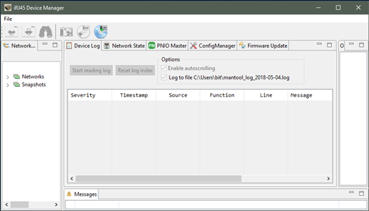
This tool is organized in panels. The “Network Navigator” shows a list of available networks. The panel “Messages” shows information regarding actions. The panel “Outline” shows additional information depending on the selected function panel.
Following function panels are available:
Panel | Function |
Device Log | shows log messages of the running application from both communication controller (CC) and application controller (AC). |
Network state | Shows link state of the available network interfaces of the RJ45 |
PNIO Master | Provides simple PNIO master functionality. |
Config Manager | Provides access to the config manager variables of the irj45. |
Firmware Update | Allows update of the firmware in the irj45. |
Device Detection
At first a communication needs to establish with the irj45. Thus, connect the irj45 to the network. Between the management PC and the irj45 a network connection must be possible.
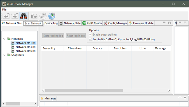
To communicate with the irj45, at first open the “Networks” list in the “Network Navigator”. Choose the network interface where the irj45 is reachable. The select the “Scan Network” button in the toolbar.
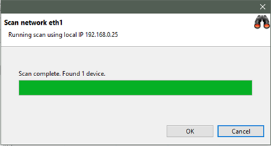
The following dialog appears and 1 found device will be reported:
As a result, a new irj45 will be shown in the „Network Navigator“ within the scanned network.
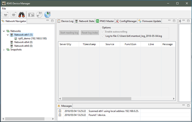
Please select the newly found irj45 for further steps.
Logging
With the selected irj45 and within the “Device Log” function panel, it now is possible to read the logging buffer using “Start reading log”. For the demo application, it shows both the log messages from the communication controller (irj45) and the application controller (Synergy Aris). Those can be distinguished by the “Source” column, which either shows “CC” ore “AC”. A successful started application reports a successful initialization of PROFINET:
[I| goal_miMctcLoop:499] running appl_setup
[I| goal_pnioNewAc:369] PROFINET Application Core successfully started
[I| appl_setup:226] Initializing device structure
[I| appl_setup:275] PROFINET ready
[I| appl_setup:281] Configuring DD
[I| appl_setup:309] DD ready
Config Manager / IP Configuration
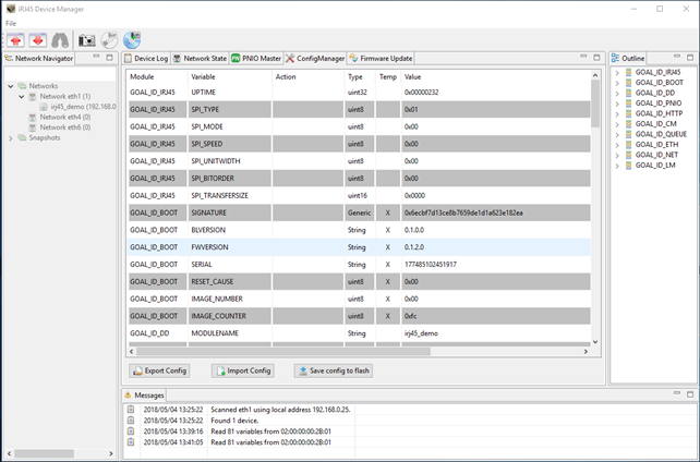
This panel provides access to the config manager variables of the irj45 (volatile and nonvolatile stored configuration variables).
To read a list of all variables, select the “Read configuration” button.
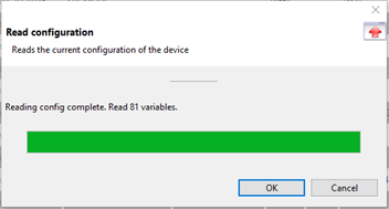
As a result, all variables with value are shown.
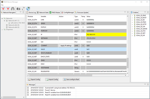
To communicate with the irj45, the IP address of the irj45 must be within the same IP network as the IP address of the Management PC IP address. Thus, chose a valid IP address and configure the irj45 accordingly.
To configure an IP address, navigate to the variables of the “Module” GOAL_ID_NET. There it is possible to configure IP, NETMASK and GW. Modify required values. Make sure the variable “VALID” is set to 1.
The Management Tool will show locally modified variables with a yellow highlight.
Those locally modified variables are downloaded to the irj45 using the “Write configuration” button in the toolbar. When prompted if changed values shall be written, answer “Yes”. Afterwards the locally modified values are transferred to the irj45, where there are only modified in RAM. To make changes permanently, use the “Save config to flash” button. Modified IP settings are applicated after restart of the system (power cycle the Aris/irj45).
Examples
01_pnio_simple_io
Please start the example “01_pnio_simple_io” according to the previous description.
To establish a PROFINET communication, at first the irj45 must be selected in the “Network Navigator”. Then select the PNIO Master function panel. At first use “Scan device” to detect the PROFINET device.
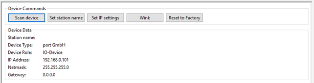
Use the “Wink” command to identify the connected irj45, which will be shown with a flashing “LED1” on the Arduino shield.
To establish a cyclic PROFINET communication use the I/O panel of the PNIO Master.

To continue, load the GSDML file provided with the distribution, located in “goal\appl\2015013_irj45\ac\gsdml\GSDML-V2.32-portGmbH-irj45-20180810.xml".
In the selector “Device Access Point” select “2-port Device”.
Afterwards press the “Connect” button. This button initiated a cyclic PROFINET communication.
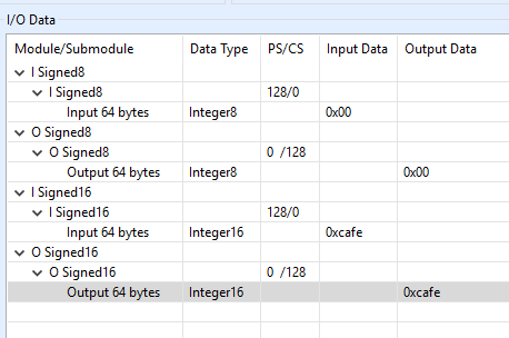
The example application on the application controller will mirror the output data to the input data.
I/O data can be manipulated and monitored in the I/O Data table. Beside that if a connection is established, the “LED1” Led on the Arduino shield will be enabled.
Process data can be monitored and manipulated using the “IO Data” panel.
02_eip_io_data
Please start the example “02_eip_io_data” according to the previous description.
To establish an Ethernet/IP communication, at first the irj45 must be selected in the “Network Navigator”. Then select the “EtherNet/IP Master” function panel. At first use “Scan device” to detect the EtherNet/IP device.

To establish an EtherNet/IP communication with the device, IP settings must be set according to the previous description. You can verify the current settings using the Management Tool.
To establish a cyclic EtherNet/IP communication use the I/O panel of the Master.

Default settings are compatible with the example. Press the “Connect” button. This button initiated a cyclic EtherNet/IP communication.
The example application on the application controller will mirror the output data to the input data.
I/O data can be manipulated and monitored in the I/O Data tables. Beside that if a connection is established, the “LED1” and “LED2” Leds on the Arduino shield will both be green.
01_udp_receive
Please start the example “01_udp_receive” according to the previous description.
This example demonstrated networking from application controller. It provides a server, listening on IP address 192.168.0.25 and port 1234 and 1235. It will mirror any data received on those ports using UDP.
Please note that this example overwrites any taken IP settings for demonstration purpose.
01_http_get
Please start the example “01_http_get” according to the previous description.
Once started this example will provide simple web server functionality. It will deliver a simple web site showing the version number of the irj45.
Please consider the correct IP settings. Those can always be checked and manipulated using the management tool.