Disclaimer
This manual represents the current state of the product. Please check with port.de for the latest version as the document may have a newer version since errors may be corrected or changes for a newer version of the product may be incorporated. Port.de assumes no responsibility for errors in this document. Qualified feedback is appreciated at service@port.de.
This document is the Intellectual Property of port.de and is intended to be used with the described product only. It may be forwarded and/or copied in the original and unmodified format. All rights reserved.
The product enables to use technologies such as PROFINET, EtherNet/IP and/or EtherCAT and others. These technologies are promoted by trade organizations, such as PNO (profibus.org), ODVA (odva.org) or ETG (ethercat.org). These trade organizations as well maintain the specification and care about legal issues.
We strongly recommend to become a member of these organisations. Most technologies are making use of patented or otherwise copyrighted technologies, approaches or other intellectual property. The membership usually automatically entitles the member for use of most of the technology-inherent copyrighted or otherwise protected Intellectual Property of the corresponding trade organization and most 3rd parties. Otherwise the user will need to obtain licenses for many patented technologies separately.
Further we suggest to you to subscribe to the corresponding Conformance Test Tool of these trade organizations. For instance the ODVA only accepts conformance test applications from companies who have a valid membership and have a valid subscription to the recent Conformance Test Tool. We as port are members in all corresponding organizations and are holding a subscription to these tools - however you as a customer need to have an own membership and an own subscription to the tool.
All rights reserved
The programs, boards and documentations supplied by port GmbH are created with due diligence, checked carefully and tested on several applications.
Nevertheless, port GmbH cannot guarantee and nor assume liability that the program, the hardware board or the documentation are error-free or appropriate to serve a specific customer purpose. In particular performance characteristics and technical data given in this document may not be interpreted to be guaranteed product features in any legal sense.
For consequential damages, every legal responsibility or liability is excluded.
port has the right to modify the products described or their documentation at any time without prior warning, as long as these changes are made for reasons of reliability or technical improvement.
All rights of this documentation are with port. Unless expressively granted - the transfer of rights to third parties or duplication of this document in any form, whole or in part, is subject to written approval by port. Copies of this document may however be made exclusively for the use of the user and his engineers. The user is thereby responsible that third parties do not obtain access to these copies.
The soft- and hardware designations used are mostly registered and are subject to copyright.
Copyright
© 2019 port GmbH
Regensburger Straße 7
D-06132 Halle
Tel. +49 345 - 777 55 0
Fax. +49 345 - 777 55 20
E-Mail service@port.de www.port.de www.port-automation.com
Changelog
Version | Changes |
1.0
|
Initial release |
1.1
|
Update to raspi shield
|
1.2 | Change network access and login data in chapter 2.2 Chapter 2.3.2 “Pre build PN-IO app” added |
Introduction
This document describes how start with the demonstration kit combining the port SoM Arduino Shield with the Raspberry Pi 3.
Within the document, special recommendations are given marked by two signs:

Special information giving hints to avoid common pitfalls when using the software
|

Special information to prevent malfunction of the software or that require special attention of the user. |
Initial Setup
The demo kit consists of
a Raspberry Pi 3 B+,
an adapter board Raspberry Header à Arduino Header,
the Arduino shield board containing the communication core,
a power supply for Raspberry Pi and
a software package
Management Tool for first steps with the device
Demo applications
Raspi shield board
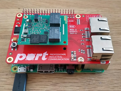
The raspi shield board comes ready to use, no configuration is required.
Preparing the Raspberry Pi
Connect the Raspberry Pi to your local network via Ethernet. The Raspberry IP address is fixed to 192.168.0.50/24. To access the device, either connect a monitor, keyboard and mouse via the provide HDMI and USB connectors or connect to the device via SSH after bootup. Consider that ssh-service is active by default! Use the following credentials for SSH access:
Username: pi
Password: pi
Starting applications
The software package for the demo kit provides several examples for the AC.
The projects to compile are available in the folder projects/2015013_irj45/ac. To compile a single project, open a shell and go to the gcc subfolder of a project e.g. projects/2015013-irj45/ac/01_pnio_mirror/gcc.
Now run make. The compile shell will now show the selection dialog for the target platform. Choose 3 for the Raspberry Pi Shield.
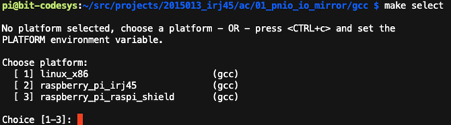
The build system will then start to build the software. The result file is stored in the subfolder build/raspberry_pi_raspi_shield and name goal_raspberry_pi_raspi_shield.bin.
If cross built copy the binary via SCP to the device. Alternatively, you can also use an USB flash drive for this purpose.
For debugging purpose it is possible to start the binary manually using following commands:
cd /home/pi/goaldmo
./goal_raspberry_pi_irj45.bin
Also see section 5 for a description of example programs.
Compilation on target
The source can be put on the raspberry pi computer and compiled there. The instructions are the same as in the previous chapter. Only for the compile step, an different approach is required.
For compiling some requirements are needed:
sudo apt-get install build-essential
In addition the SPI interface needs to be enabled using raspi-config.
sudo raspi-config
Under “Interface options” it os possible to enable the SPI interface.
For compilation call make the following way:
make CROSS_COMPILE=
This will call the native gcc compiler instead of the cross compiler, thus natively compiling the binary on the raspberry pi.
Management Tool
The Management Tool allows development related configuration and management of the application. This management is based on a UDP broadcast communication. Thus, it works independently from IP settings of the management PC and SoM.
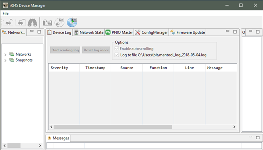
This tool is organized in panels. The “Network Navigator” shows a list of available networks. The panel “Messages” shows information regarding actions. The panel “Outline” shows additional information depending on the selected function panel.
Following function panels are available:
Panel | Function |
Device Log | Shows log messages of the running application from both communication controller (CC) and application controller (AC). |
Network state | Shows link state of the available network interfaces of the SoM. |
PNIO Master | Provides simple PNIO master functionality. |
ConfigManager | Provides access to the config manager variables of the SoM. |
Firmware Update | Allows update of the firmware of the SoM. |
Device Detection
At first a communication needs to establish with the SoM. Thus, connect the SoM to the network. Between the management PC and the SoM a network connection must be possible.
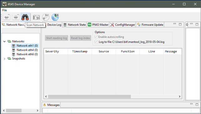
To communicate with the SoM, at first open the “Networks” list in the “Network Navigator”. Choose the network interface where the SoM is reachable. Then select the “Scan Network” button in the toolbar.
The following dialog appears and 1 found device will be reported:
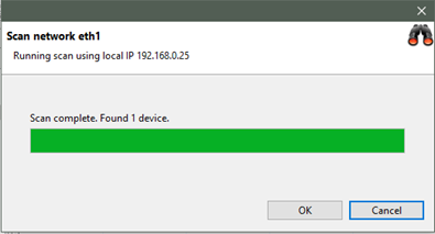
As a result, a new SoM will be shown in the „Network Navigator“ within the scanned network.
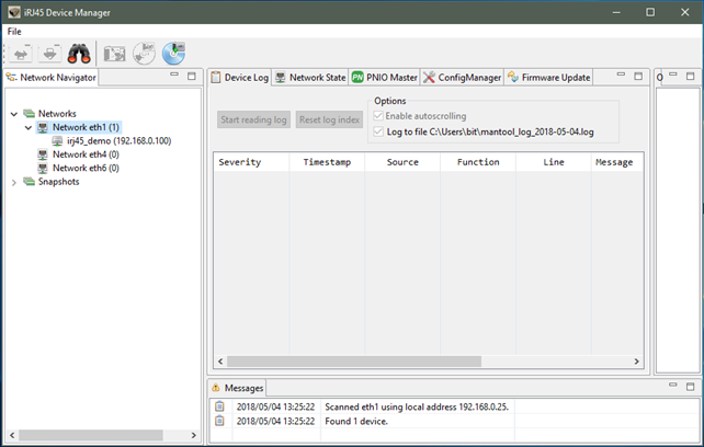
Please select the newly found SoM for further steps.
Logging
With the selected SoM and within the “Device Log” function panel, it is now possible to read the logging buffer using “Start reading log”. For the demo application, it shows both the log messages from the communication controller (SoM) and the application controller (Raspberry Pi). Those can be distinguished by the “Source” column, which either shows “CC” ore “AC”. A successful started application reports a successful initialization of PROFINET:
[I| goal_miMctcLoop:499] running appl_setup
[I| goal_pnioNewAc:369] PROFINET Application Core successfully started
[I| appl_setup:226] Initializing device structure
[I| appl_setup:275] PROFINET ready
[I| appl_setup:281] Configuring DD
[I| appl_setup:309] DD ready
To stop logging push the button again.
Config Manager / IP Configuration
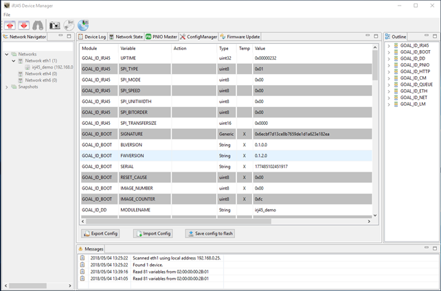
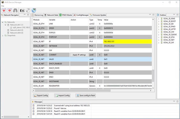
The function panel “ConfigManager” provides access to the config manager variables of the SoM (volatile and nonvolatile stored configuration variables).
To read a list of all variables, select the “Read configuration” button in the toolbar.
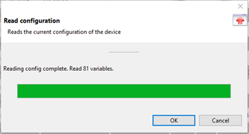
As a result, all variables with value are shown.
To communicate with the SoM, the IP address of it must be within the same IP network as the IP address of the Management PC IP address. Thus, choose a valid IP address and configure the SoM accordingly.
To configure an IP address, navigate to the variables of the “Module” GOAL_ID_NET. Make sure, that the variable DHCP_ENABLED is set to 0x00. Now it is possible to configure IP, NETMASK and GW. Modify required values. Set the variable “VALID” to 0x01.
The Management Tool will show locally modified variables with a yellow highlight.
Those locally modified variables are downloaded to the SoM using the “Write configuration” button in the toolbar. When prompted if changed values shall be written, answer “Yes”. Afterwards the locally modified values are transferred to the SoM, where there are only modified in RAM. To make changes permanently, answer the following prompt with “Yes”. Modified IP settings are applicated after restart of the system (power cycle the Raspberry Pi/SoM).
Examples
01_pnio_simple_io
Please start the example “01_pnio_simple_io” according to the previous descriptions.
To establish a PROFINET communication, at first the SoM must be selected in the “Network Navigator”. Then select the function panel PNIO Master. At first use “Scan device” to detect the PROFINET device.
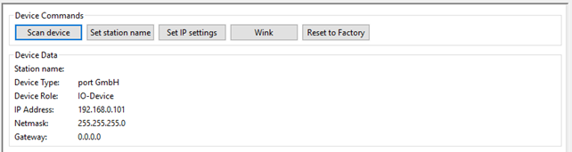
Use the “Wink” command to identify the connected SoM, which will be shown with a flashing “LED1” on the Arduino shield.
To establish a cyclic PROFINET communication use the I/O panel of the PNIO Master.
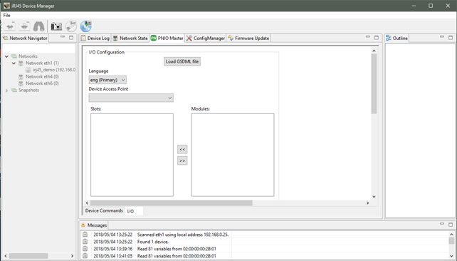
To continue, load the GSDML file provided with the distribution, located in “goal\appl\2015013_irj45\ac\gsdml\GSDML-V2.32-portGmbH-irj45-20180810.xml".
In the selector “Device Access Point” select “2-port Device”.
Afterwards press the “Connect” button. This button initiated a cyclic PROFINET communication.
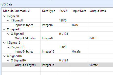
The example application on the application controller will mirror the output data to the input data. I/O data can be manipulated and monitored in the I/O Data table. Beside that if a connection is established, the “LED1” Led on the Arduino shield will be enabled.
Process data can be monitored and manipulated using the “IO Data” panel.
02_eip_io_data
Please start the example “02_eip_io_data” according to the previous description.
To establish an EtherNet/IP communication, at first the SoM must be selected in the “Network Navigator”. Then select the “EtherNet/IP Master” function panel. At first use “Scan device” to detect the EtherNet/IP device.
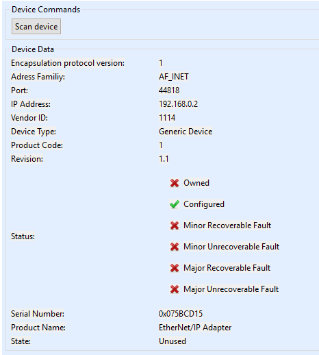
To establish an EtherNet/IP communication with the device, IP settings must be set according to the previous description. You can verify the current settings using the Management Tool.
To establish a cyclic EtherNet/IP communication use the “I/O Data” panel of the Master.
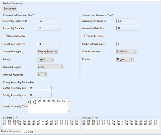
Default settings are compatible with the example. Press the “Connect” button. This button initiated a cyclic EtherNet/IP communication.
The example application on the application controller will mirror the output data to the input data.
I/O data can be manipulated and monitored in the I/O Data tables. Beside that if a connection is established, the “LED1” and “LED2” Leds on the Arduino shield will both be green.
01_udp_receive
Please start the example “01_udp_receive” according to the previous description.
This example demonstrated networking from application controller. It provides a server, listening on IP address 192.168.0.25 and port 1234 and 1235. It will mirror any data received on those ports using UDP.
Please note that this example overwrites any taken IP settings for demonstration purpose.
01_http_get
Please start the example “01_http_get” according to the previous description.
Once started this example will provide simple web server functionality. It will deliver a simple web site showing the version number of the SoM.
Please consider the correct IP settings. Those can always be checked and manipulated using the management tool.