...
...
...
...
...
...
...
...
...
...
...
...
...
...
...
...
...
...
...
...
...
...
...
...
...
...
...
...
...
...
...
...
...
...
...
...
...
Cyclic Data Exchange
The communication with the irj45 iRJ45 module/ SoM uses the well-known Serial Peripheral Interface (SPI) or with the Firmware Version 2.2.0.0 the Universal Asynchronous Receiver / Transmitter Protocol (UART).
A cyclic transfer must always be triggered by the application core (AC) and must at least be once during the heartbeat timeout. The implementation in the irj45 iRJ45/ SoM updates the SPI cyclic data after each transfer to make sure it doesn't interrupt a running transfer.
Clock domains and communication cycle
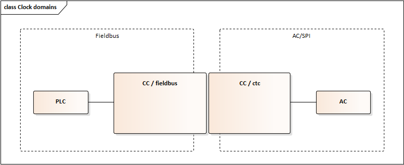
Figure 1 ctc clock domains
Operation of the device includes two clock domains, which run independently of each other. First clock domain is the fieldbus side. Commonly the PLC interacts with the device in one clock domain, where the PLC controls the timing of the output data. Second clock domain is drived driven by the AC through initiation of the SPI ctc-cycle, which reads the output data from the device and updates input data for the next fieldbus cycle. Therefore, a specific timing of the process data is set up as shown in Figure 2 Communication Cycle.
...
New output data from PLC
Processing of output data in CC module and preloading of SPI cyclic transfer buffer
A finished SPI cyclic transfer initiated by the AC executes data exchange between AC and CC
Preloading of new input data for the next SPI cyclic transfer
A finished sequential SPI cyclic transfer executes data exchange between AC and CC, thus providing new input data for the next fieldbus transfer
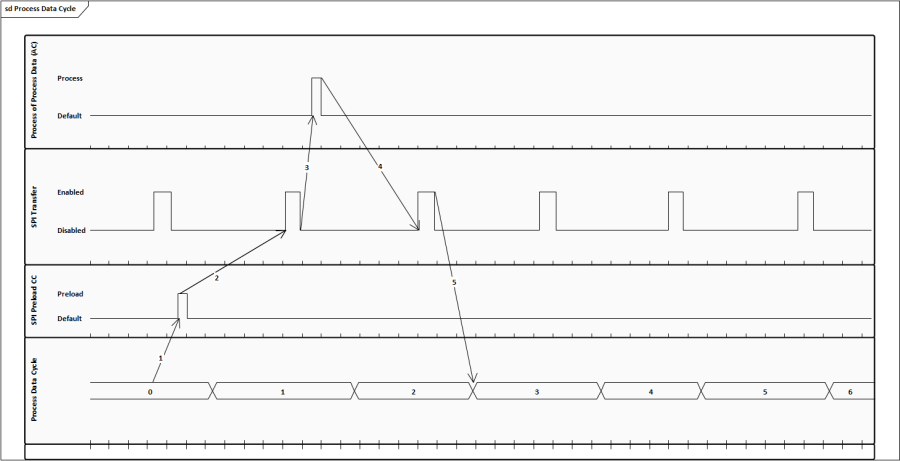
Figure 2 Communication Cycle
Technical data
Transfer length:
Cyclic only: 72 Bytes
Cyclic + RPC data: 128 Bytes
Baud-rate:
at SPI: max. 10 Mbps, usually
2 Mbps.
at UART: max. 921600 baud/s.
Delay between cyclic transfer:
SPI
: 0.5 ms... Heartbeat Timeout (1 second)
UART: 2 ms… Heartbeat Timeout (1 second)
Minimal round-trip time: 4 ... 6 ms (depending on the used protocol and setup)
...
Following simplified diagram shows basic SPI timing which must be considered by the application controller.
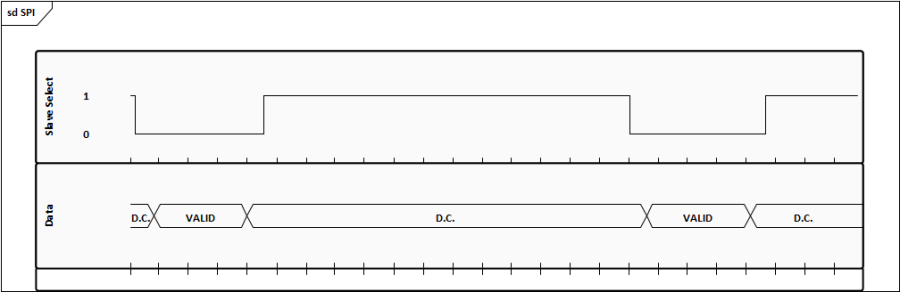
Figure 3 Basic SPI timing
SPI Speed
The communication module supports SPI speed in the range of 29.3 kHz and 10MHz. Default SPI speed is 2MHz.
...
This time is the distance between two consecutive SPI transfers. Between two transfers a minimum time of 250 us must be kept to secure proper processing in the module.
...
Cyclic Frame Structure
The SPI cyclic frame must contain the structure from Table 18: SPI Frame Structure to get accepted by the irj45 iRJ45 module/ SoM.
Bytes | Byte | Byte | Bytes | Bytes |
Fletcher-16 | Sequence | Data Length | Cyclic Data | RPC Data |
Table 18 SPI Frame Structure
The same layout is send back by the device containing its local sequence counter. The sequence counter is tracked and if it doesn't change during the heartbeat timeout the communication gets stopped until the sequence is updated again.
...
If only cyclic data is transferred the data length can be set from 0 to 73 bytes. When using RPC over SPI the data length needs to have a fixed value of 124.
...
The RPC protocol used by the Micro Core-To-Core (MCTC) implementation of the irj45 iRJ45 module is transferred in byte 77 – 127. RPC transfers are always acknowledged to minimize data loss on erroneous transfers as good as possible. Also the RPC calls can be larger than the available 50 bytes as the irj45 iRJ45 module internally stores each received RPC frame in a ring-buffer and waits until a partitioned transfer is completed before proceeding with the request.
...
The RPC frame must contain the structure from Table 19: RPC Frame Structure to be accepted by the irj45 iRJ45 module.
Bytes | Byte | Byte | Byte | Byte | Bytes |
Fletcher-16 | Local | Remote | Data | Flags | Data |
Table 19 RPC Frame Structure
Each time a new local sequence is sent the irj45 iRJ45 will respond with the corresponding acknowledge in the second transferred frame. If no acknowledge was received the AC can retransmit its frame to re-request the acknowledge.
...
The sequence counter must be incremented for each RPC frame with changed data. For each unseen incremental frame the irj45 iRJ45 module will put the transferred data into its internal ring-buffer and after the length matches it will process the RPC call.
...
For each processed received RPC frame the AC needs to send out an acknowledge. If the received frame doesn't match the expected sequence the AC must leave the acknowledge on the previous sequence to trigger a resend from the irj45 iRJ45 module. If the resend fails the AC can also perform a re-sync.
...
Contains the length of the RPC data and must be between 0 (acknowledge-only frame) and 44.
Flags (8 Bit)
Bit | Bit | Bit | Bit |
Sync Request | Sync Acknowledge | Reserved | Request Acknowledge |
Table 20 RPC Header Flags
Sync Request
If set to 1 the irj45 iRJ45 module enters the RPC synchronization.
...
RPC Synchronization
Before the irj45 iRJ45 module is ready to operate and after a synchronization is lost the RPC must be synchronized. This is triggered by setting the Sync Request flag to 1.
AC |
iRJ45 Module | |
Sync Request = 1 | |
Sync Request = 1 | |
Sync Request = 0 | |
RPC_Receive() | |
RPC_Receive() | |
RPC_Receive() |
Table 21 RPC Synchronization
After the synchronization has finished the irj45 iRJ45 both devices must initiate the generic RPC call SetupStateGet to verify if the partner device is in the same state. If one partner is already configured but the other is not, than the configured parter must reboot and the synchronization starts again.
...
If the AC successfully passed the synchronization stage and configured the irj45 iRJ45 module it must call the RPC API SetupDone. At this point the irj45 iRJ45 module is ready for normal operation.
...
An RPC request/response consists of the parts shown in Table 21 and Table 22.
Byte 0..1 | Byte 2..5 | Byte 6 .. x | Byte x+1 .. x+4 | Byte x+5..x+8 | Byte x+9 | Byte x+10 | Byte (x+11) .. (x+14) |
Static Identifier | Data Length | Data | Function Id | RPC Id(little endian) | CTC Id | Flags | Fletcher-16 |
Table 22 RPC Request Structure
Byte 0..1 | Byte 2..5 | Byte 6 .. x | Byte x+1 | Byte x+2 | Byte (x+3)..(x+4) |
Static Identifier | Data Length | Response Data | CTC Id | Flags | Fletcher-16 |
Table 23 RPC Response Structure
Static Identifier
The 2 byte static identifier is used on the irj45 iRJ45 module to detect the start of a new RPC request or response. If the identifier is also contained in the data bytes the Fletcher-16 checksum will make sure that it don't gets threaded like an RPC request/response.
...
The flags define the type of the request, see Table 5: RPC Request/Response Flags for details.
Bit 0..1 |
0 – Response1 – Request |
Table 24 RPC Request/Response Flags
Data
The data part contains the virtual stack of the RPC request/response.
...
The API goal_pnioDmSubslotAdd maps input and output data of the given subslot to the also given instances of the DM.
Parameter | Description |
GOAL_PNIO_T *pPnio | GOAL PROFINET instance |
uint32_t idMiDmPeerFrom | Handle that receives data from CC |
uint32_t idMiDmPeerTo | Handle that sends data to CC |
GOAL_MI_DM_PART_T **ppPartDataOut | Output pointer to store the DM partition |
GOAL_MI_DM_PART_T **ppPartDataIn | Output pointer to store the DM partition |
uint32_t idApi | API id |
uint16_t idSlot | Slot id |
uint16_t idSubslot | Subslot id |
uint32_t lenDataOut | Output data length |
uint32_t lenDataIn | Input data length |
Table 25 goal_pnioDmSubslotAdd API Description
Map Subslot IOCS/IOPS - goal_pnioDmSubslotIoxsAdd
The API goal_pnioDmSubslotIoxsAdd maps IOCS and IOPS states of the given subslot to the given instances of the DM.
Parameter | Description |
GOAL_PNIO_T *pPnio | GOAL PROFINET instance |
uint32_t idMiDmPeerFrom | Handle that receives data from CC |
uint32_t idMiDmPeerTo | Handle that sends data to CC |
GOAL_MI_DM_PART_T **ppPartIocsOut | Output pointer to store the DM partition |
GOAL_MI_DM_PART_T **ppPartIopsOut | Output pointer to store the DM partition |
GOAL_MI_DM_PART_T **ppPartIocsIn | Output pointer to store the DM partition |
GOAL_MI_DM_PART_T **ppPartIopsIn | Output pointer to store the DM partition |
uint32_t idApi | API id |
uint16_t idSlot | Slot id |
uint16_t idSubslot | Subslot id |
Table 26 : goal_pnioDmSubslotIoxsAdd API Description
Map APDU Status – goal_pnioDmApduAdd
The API goal_pnioDmApduAdd maps the APDU status to the given instance of the DM.
Parameter | Description |
GOAL_PNIO_T *pPnio | GOAL PROFINET instance |
uint32_t idMiDmPeerTo | (ignored) Handle that sends data to CC |
GOAL_MI_DM_PART_T **ppPartApduOut | Output pointer to store the DM partition |
Table 27 goal_pnioDmApduAdd API Description
Map Data Provider Status – goal_pnioDmDpAdd
The API goal_pnioDmDpAdd maps the Data Provider status to the given instance of the DM.
Parameter | Description |
GOAL_PNIO_T *pPnio | GOAL PROFINET instance |
uint32_t idMiDmPeerTo | (ignored) Handle that sends data to CC |
GOAL_MI_DM_PART_T **ppPartDp | Output pointer to store the DM partition |
Table 28 goal_pnioDmApduAdd API Description